Product Description
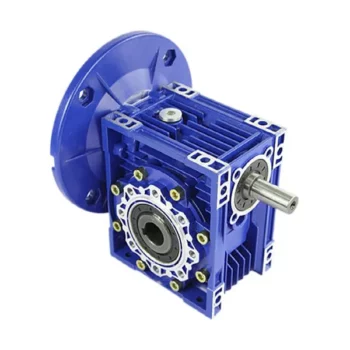
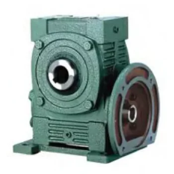
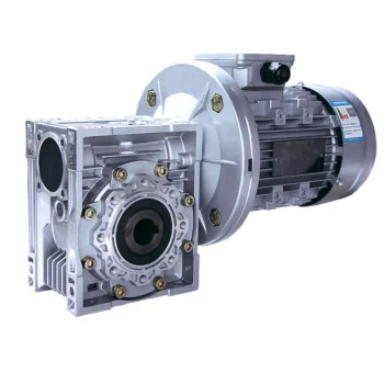
Brief introduction to RV series worm gear speed reducer
SMRV series worm-gear speed reducer is a new-generation of products developed by our company with combination of advanced technology
both at home and abroad. lt features in:
1.Auminium alloy die-cast casing for RV571, NMRV030,NMRV040,NMRV050,NMRV063,NMRV075,NMRV090, light weight and non-rusting;
cast iron casing for NMRV110,NMRV130,NMRV150
2. Large output torque.
3. Stable transmission with lower noise.
4. High heat-radiating efficiency.
5. Elegant shape, small volume and durable serving life.
6. Suitable for omnibearing installation.
Technical performance and selection reference
| Motor Power | Model | Speed Ratio | n2(r/min) | M2n(NM) |
| 0.12kw | NMRV050 | 50~100 | 28~14rpm | 26~39N.M |
| 0.18kw | NMRV050 | 40~100 | 35~14rpm | 33~59N.M |
| 0.25kw | NMRV050 | 20~80 | 70~17.5rpm | 27~72N.M |
| 0.37kw | NMRV050 | 10~60 | 140~23.3rpm | 21~89N.M |
| 0.55kw | NMRV050 | 5~30 | 280~46.7rpm | 17~80N.M |
| 0.75kw | NMRV050 | 5~30 | 280~46.7rpm | 23~112N.M |
Note recommendations
To install the reduction unit it is necessary tonote the following recommendations:
1. Check the correct direction of rotation of thereduction unit output shaft before fitting the unit tothe machine.
2. Before mount with the prime moveanddevice,please check the reducers every axiadiameter, aperture,key and key slot,
to be theirdimensions are not deviation, and avoidassembaurtoo tight or too loose, unless it wilinfluence the reducer’s performance.
3. The mounting on the machine must be stableto avoid anv vibration.
4.Whenever possible,protect the reductiorunit against solar radiation and bad weather.
5.In the case of particularly lengthy periods ofstorage (4-6 months), if the oil seal is not immersedin the lubricant inside the unit.
It is recommended tochange it since the rubber could stick to the shaft ormay even have lost the elasticity it needs to functionproperly.
6.Painting must definitely not go over rubberparts and the holes on the breather plugs, if any.
7.When connect with hollow or CHINAMFG shaftplease grease the joint to avoid lock or oxidation.
8.Check the correct level of the lubricantthrough the indicator, if there is one.
9. Starting must take place gradually, withoutimmediately applying the maximum load
10. Supporting unit is required when usingvarious of reducer matched with motor directiy andthe wsight of motor is a little bigger than common.
11 .Ensure the motor cools correctly byassuring good passage of air from the fan side.
12. In the case of ambient temperatures+40°C call the Technical Service.
/* January 22, 2571 19:08:37 */!function(){function s(e,r){var a,o={};try{e&&e.split(“,”).forEach(function(e,t){e&&(a=e.match(/(.*?):(.*)$/))&&1
| Application: | Motor, Electric Cars, Motorcycle, Machinery, Marine, Toy, Agricultural Machinery, Car |
|---|---|
| Function: | Distribution Power, Clutch, Change Drive Torque, Change Drive Direction, Speed Changing, Speed Reduction, Speed Increase |
| Layout: | Cycloidal |
| Samples: |
US$ 36.4/Piece
1 Piece(Min.Order) | Order Sample |
|---|
| Customization: |
Available
| Customized Request |
|---|
.shipping-cost-tm .tm-status-off{background: none;padding:0;color: #1470cc}
|
Shipping Cost:
Estimated freight per unit. |
about shipping cost and estimated delivery time. |
|---|
| Payment Method: |
|
|---|---|
|
Initial Payment Full Payment |
| Currency: | US$ |
|---|
| Return&refunds: | You can apply for a refund up to 30 days after receipt of the products. |
|---|

Calculating Gear Ratio in a Worm Reducer
The gear ratio in a worm reducer is determined by the number of teeth on the worm wheel (also known as the worm gear) and the number of threads on the worm shaft. The gear ratio formula for a worm reducer is:
Gear Ratio = Number of Teeth on Worm Wheel / Number of Threads on Worm Shaft
For example, if the worm wheel has 60 teeth and the worm shaft has a single thread, the gear ratio would be 60:1.
It’s important to note that worm reducers have an inherent self-locking property due to the angle of the worm threads. As a result, the gear ratio also affects the mechanical advantage and the system’s ability to resist backdriving.
When calculating the gear ratio, ensure that the worm reducer is properly designed and that the gear ratio aligns with the desired mechanical characteristics for your application. Additionally, consider factors such as efficiency, load capacity, and speed limitations when selecting a gear ratio for a worm reducer.

Worm Gearbox vs. Helical Gearbox: A Comparison
Worm gearboxes and helical gearboxes are two popular types of gear systems, each with its own set of advantages and disadvantages. Let’s compare them:
| Aspect | Worm Gearbox | Helical Gearbox |
| Efficiency | Lower efficiency due to sliding friction between the worm and worm wheel. | Higher efficiency due to rolling contact between helical gear teeth. |
| Torque Transmission | Excellent torque transmission and high reduction ratios achievable in a single stage. | Good torque transmission, but may require multiple stages for high reduction ratios. |
| Noise and Vibration | Generally higher noise and vibration levels due to sliding action. | Lower noise and vibration levels due to smoother rolling contact. |
| Backlash | Higher inherent backlash due to the design. | Lower backlash due to meshing of helical teeth. |
| Efficiency at Higher Speeds | Less suitable for high-speed applications due to efficiency loss. | More suitable for high-speed applications due to higher efficiency. |
| Overload Protection | Natural self-locking feature provides some overload protection. | May not have the same level of inherent overload protection. |
| Applications | Commonly used for applications requiring high reduction ratios, such as conveyor systems and heavy-duty machinery. | Widely used in various applications including automotive transmissions, industrial machinery, and more. |
Both worm and helical gearboxes have their place in engineering, and the choice between them depends on the specific requirements of the application. Worm gearboxes are preferred for applications with high reduction ratios, while helical gearboxes are chosen for their higher efficiency and smoother operation.

Preventing Backlash in a Worm Gearbox
Backlash in a worm gearbox can lead to reduced accuracy, positioning errors, and decreased overall efficiency. Here are steps to prevent or minimize backlash:
- High-Quality Components: Use high-quality worm gears and worm wheels with tight manufacturing tolerances. Precision components will help reduce backlash.
- Proper Meshing: Ensure the worm gear and worm wheel are properly aligned and meshed. Improper meshing can lead to increased backlash.
- Preload: Applying a small amount of preload to the worm gear can help reduce backlash. However, excessive preload can increase friction and wear.
- Anti-Backlash Mechanisms: Consider using anti-backlash mechanisms, such as spring-loaded systems or adjustable shims, to compensate for any inherent backlash.
- Lubrication: Proper lubrication can reduce friction and play a role in minimizing backlash. Use a lubricant that provides good film strength and reduces wear.
- Maintenance: Regularly inspect and maintain the gearbox to identify and address any changes in backlash over time.
It’s important to strike a balance between reducing backlash and maintaining smooth operation. Consulting with gearbox experts and following manufacturer guidelines will help you optimize your worm gearbox’s performance while minimizing backlash.


editor by CX 2024-03-08
